Introduction Every vacuum contactor catalogue prints a rated electrical life, often several hundred thousand operations. No nameplate states how much ...
Every vacuum contactor catalogue prints a rated electrical life, often several hundred thousand operations. No nameplate states how much of that life the unit in front of you has already spent. And unlike a brake pad, the part that wears cannot be inspected: the contacts sit inside a sealed vacuum interrupter and stay invisible for the whole service life. Judging vacuum contactor contact wear is therefore a measurement task, not an inspection task.
This article is for the reader who already has a unit, a test sheet or a record, and needs a verdict rather than an explanation. It sets out what wears, which numbers define the limit, how to measure them, and where the line falls between keep running, watch closely and replace. For the budget side of the question, see our guide to vacuum contactor electrical life.
The phrase contact wear covers three different things. Until they are separated, no measurement produces a verdict.
Table 1 — Three wear surfaces and what each one demands
|
Surface |
Wear mechanism |
Judging quantity |
At the limit |
|
Interrupter contacts |
Arc erosion per interruption |
Overtravel, loop resistance, operations |
Low contact force, temperature rise, welding |
|
Operating mechanism |
Mechanical wear at bearings and pins |
Operating time, stroke, noise, mechanical count |
Incomplete closing, pole discrepancy |
|
Auxiliaries and connections |
Thermal cycling, loosening, oxidation |
Joint torque, contact resistance |
Local overheating |
The three age on different clocks. A mechanism may be rated for a million operations while contact electrical life is a quarter to a tenth of that, so on most installations the contacts set the replacement date — unless the unit is operated far more often unloaded than loaded.
A vacuum interrupter is sealed. Contacts, bellows and shield sit inside the envelope, so nothing visible outside reports what is happening within it. A clean, uncracked bottle can be close to its limit.
That overturns the commonest field practice: open the cubicle door, look at the interrupter, declare the contactor serviceable.
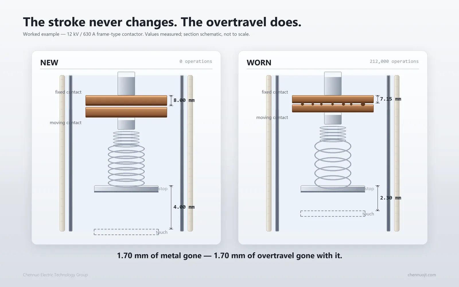
The rule is short. Contact wear can be measured, not seen: as the contact faces erode, the travel that builds contact pressure erodes with them, while the mechanism still closes to the same apparent position.
Figure 1 — New and worn contacts: overtravel falls as contact thickness falls
Three figures limit a contactor at once, on different clocks. Most wrong decisions come from watching only one.
· Rated electrical life — load-breaking operations by utilization category. AC-3 and AC-4 differ by a factor, not a percentage. This is the count budget.
· Mechanical life — no-load operations, usually well above the electrical figure and rarely the binding constraint.
· Wear limit — the permitted erosion or minimum overtravel for that model. This is the dimension budget.
One budget is spent at a rate you estimate, the other at a rate you can measure. Whichever runs out first decides.
Figure 2 — Three limits on one timeline: the count is a budget, the overtravel is the truth
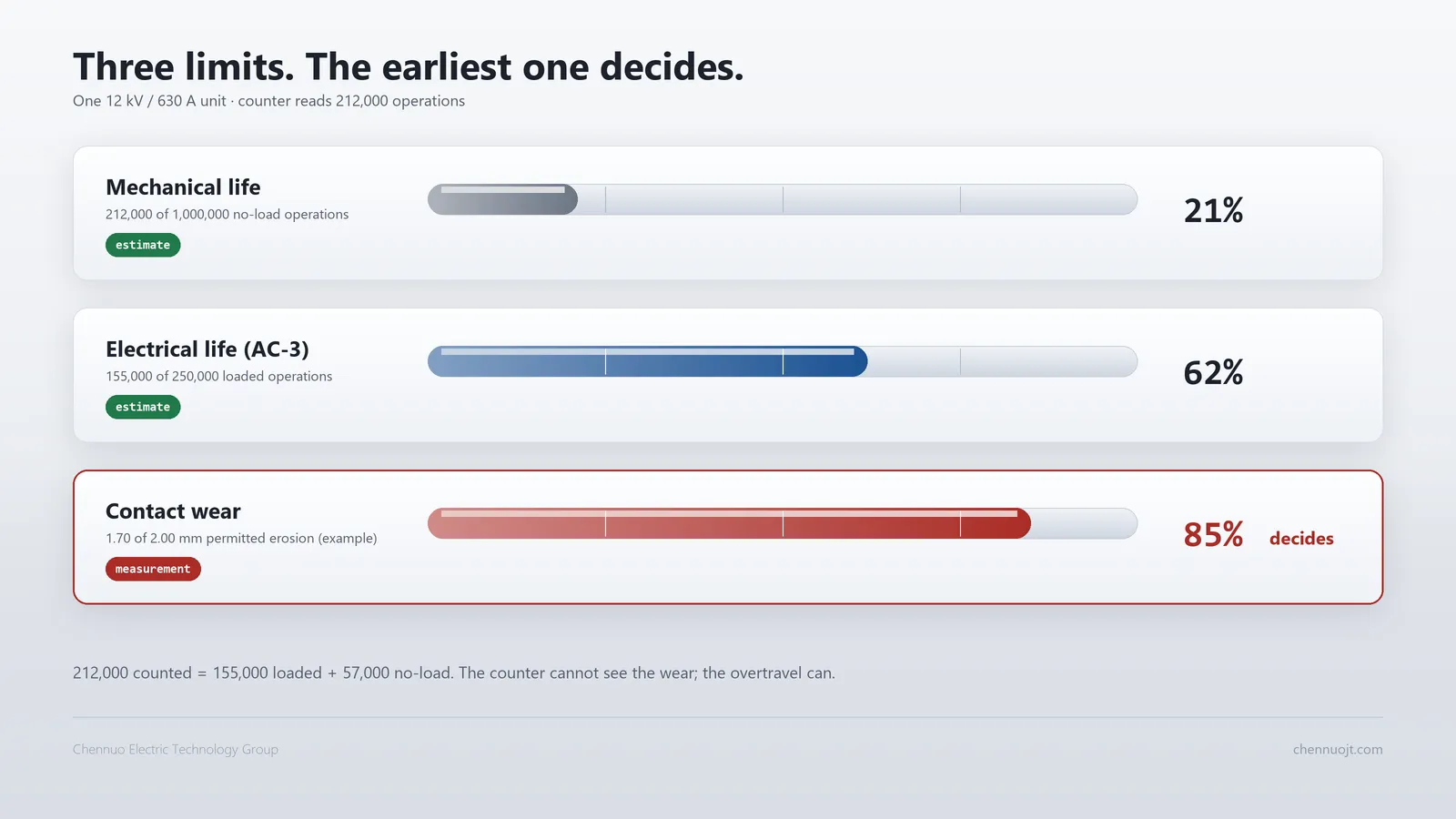
The same count does not mean the same erosion. Breaking current, power factor and jogging duty each change how much metal leaves the contact faces per operation, so two identical units on identical counts can sit at very different points of wear.
The count is also approximate: some counters register closing operations only, some began mid-life, some have had an auxiliary switch replaced.
So the counter estimates what has been spent, while overtravel and loop resistance read what is left. When they disagree, trust the measurement — the divergence behind every unit that fails before its rated count, as set out in our article on vacuum contactor failure causes.
Four quantities carry the diagnosis. For each, the question is how it moves, and what it is compared against.
Overtravel, or wipe, is the travel the moving contact is pushed beyond first touch. It builds contact pressure, and everything downstream follows from it. Worn contacts are thinner, so overtravel falls by the material lost.
That makes it the closest reading of how much contact remains, and the reason minimum overtravel is usually the primary limit. The datum differs with construction, so procedure and limit belong to the model, not the family.
A healthy pair reads in micro-ohms, which dictates the instrument: a four-wire micro-ohmmeter with separate current and voltage leads. An insulation tester measures a quantity several orders of magnitude away.
What carries meaning is the ratio to the baseline; investigation commonly begins around 1.2 to 1.5 times it, with the manufacturer's threshold taking precedence. Fix the probe position and record the temperature, or the trend says nothing.
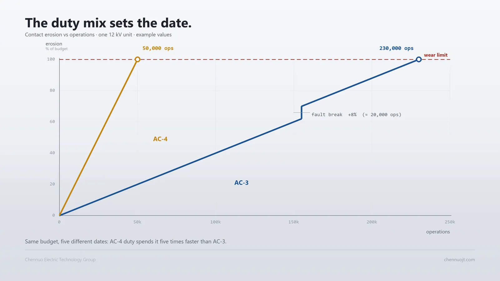
A single total hides the duty mix. One AC-4 operation is not one AC-3 operation, and a fault interruption is neither. Accumulate per category, or convert heavy duty with the manufacturer's factors.
Fault interruptions need their own ledger: one high-current break can erode as much as many rated operations and never appears in the counter. Figure 3 shows both: a steeper AC-4 slope, and a step where the fault was interrupted.
Figure 3 — Wear against operations: AC-3 and AC-4 slopes, with a fault interruption as a step
Opening distance is the total stroke; overtravel is how much remains as pressure. Both shrinking together means wear is late, and opening distance alone misses the decisive number.
On the values themselves. Permitted erosion, minimum overtravel, measurement datums and conversion factors are model-specific, and differ between frame-type and encapsulated designs. Confirm each against the manual for the unit.
Two measurements carry most of the decision. Both are simple; repeating them the same way, on the same point, at every interval, is not.
Safety. All measurements described here are made with the contactor de-energised. Isolate, prove dead, discharge, earth and confirm the isolation under the site permit-to-work procedure, using calibrated instruments and qualified personnel. This section describes method only; it does not replace the manufacturer's manual or the site's safety rules.
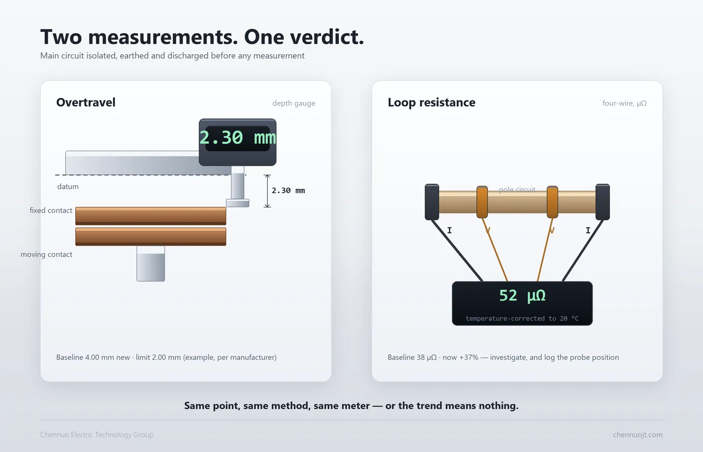
With the contactor closed, measure the penetration of the moving contact against the datum the manual specifies, using the gauge it calls for.
· Same datum as the manual — another reference face invalidates every comparison that follows.
· All three poles, separately — the spread is itself a finding, pointing to single-pole wear or a misaligned mechanism.
· Before and after any adjustment — so the effect is known rather than assumed.
Inject current and measure voltage at separate points, clear of paint and oxide, taking each pole and recording the value with temperature and probe position. Read it three ways: against the unit's own baseline, against identical units in the same switchboard, against others from the batch. One value has no context.
The point of both is repeatability rather than precision: same point, same method, same instrument.
Figure 4 — Overtravel measurement and four-wire loop resistance measurement
Two things stay out of reach. Vacuum integrity needs dedicated equipment such as magnetron discharge testing. Residual contact thickness needs dismantling or manufacturer tooling.
So the field verdict rests on overtravel, loop resistance and counted operations, cross-checked; vacuum integrity runs on its own cycle, covered in our guide to vacuum interrupter testing.
The measurement becomes useful only when it turns into one of three words. The boundaries are structural; the numbers defining them come from the manual, not from this article.
Table 2 — Three zones, three actions
|
Zone |
Overtravel |
Loop resistance |
Action |
|
OK |
Above the minimum, close to baseline |
Close to baseline |
Continue the normal monitoring cycle |
|
WATCH |
Approaching the minimum, or pole spread widening |
Above roughly 1.2 times baseline |
Shorten the interval, pre-order spares, plan the outage |
|
REPLACE |
At or below the minimum permitted value |
Clearly rising on a consistent trend |
Schedule replacement, do not wait for the next outage |
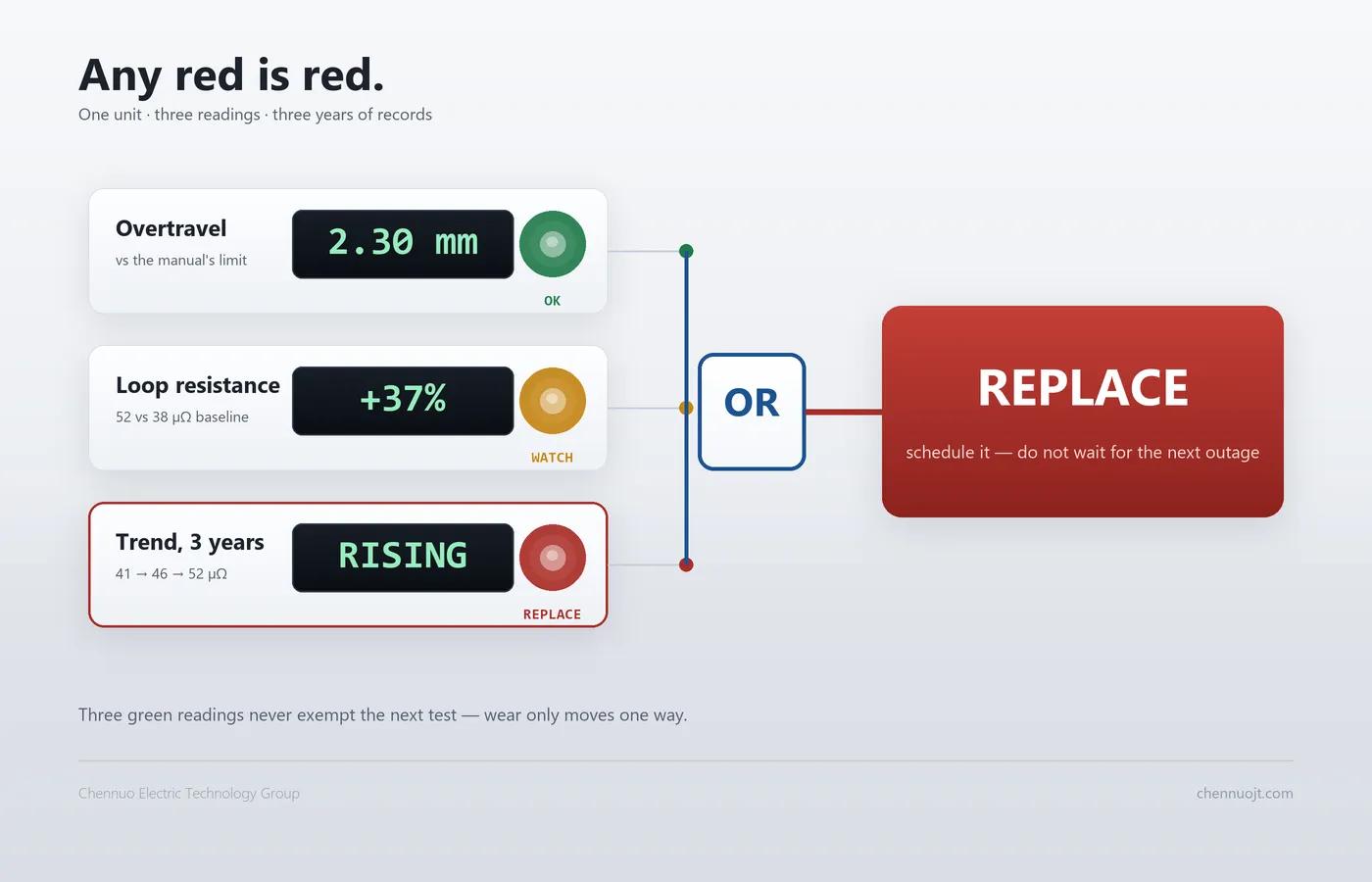
The rule is deliberately asymmetric: any single item in REPLACE makes the verdict REPLACE. Requiring all three to agree would mean waiting for corroboration the equipment will not provide in time.
The reverse does not hold. Three OK readings do not exempt a unit from the next test, because wear moves in one direction only. Today's OK means not yet.
Figure 5 — Any single red is a red
A single reading answers whether the limit has been crossed. A series answers how long is left, which is what drives planning and budgeting.
The minimum for a usable series is a date, a temperature, a measuring point and a name on every record. Under those conditions the difference between two readings carries more than either reading alone.
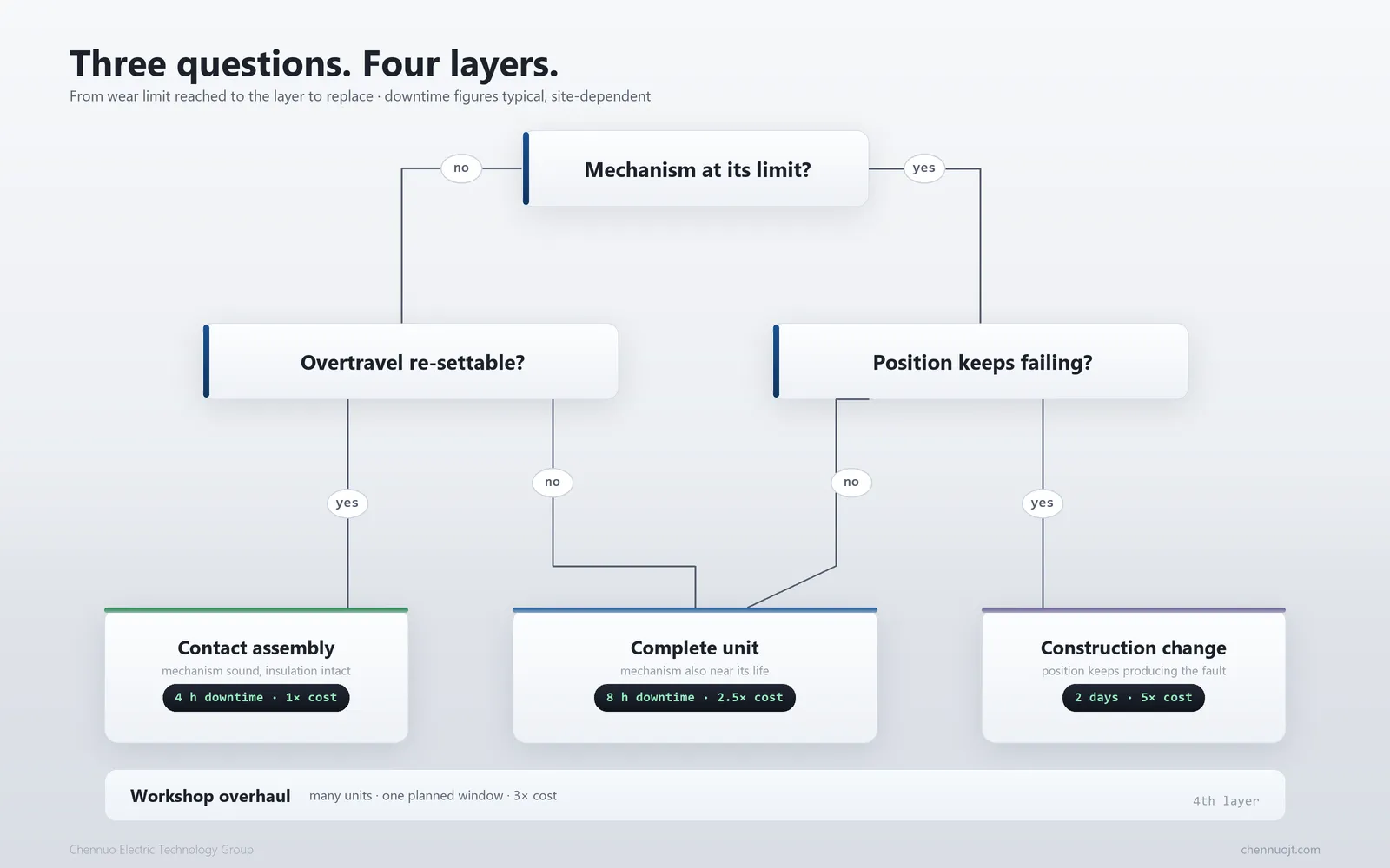
Replacement is not one decision but four, differing by an order of magnitude in cost and downtime. The measurement says the limit is reached, not what to replace.
Table 3 — Four replacement layers and when each one applies
|
Layer |
Applies when |
Note |
|
Contact or interrupter assembly |
Mechanism sound, insulation intact, contacts the only item at limit |
Least costly; usual on frame-type units, while encapsulated designs go as a complete unit |
|
Complete unit, same model |
Mechanism near its life, or several parts degrading together |
Controlled downtime, original performance |
|
Complete unit, construction change |
The position itself keeps producing the same problem |
Covered in 6.3 |
|
Workshop overhaul |
Many units, a planned window, panel dimensions to keep |
Longer turnaround, suits planned maintenance |
The first row is where spare interrupters and assemblies for 7.2 kV and 12 kV units do most of their work; lead time and batch matching then matter more than price.
Contacts at the limit with a sound mechanism usually means an assembly replacement — provided overtravel can be readjusted afterwards and pole synchronism checked in the same visit.
If the mechanism is also at its limit — near mechanical life, abnormal noise, stroke drift — new contacts will not fix it. After fitting, can overtravel be brought back to specification? If not, the transmission is worn.
Some positions keep producing condensation, pollution or complaints about exposed live parts. Replacing parts there reproduces the result.
An encapsulated cylinder-type contactor puts the primary insulation in solid insulation and removes most exposed creepage surface, which changes the outcome there. It is a different trade, not a better one everywhere: frame-type units stay easier to inspect and re-piece (frame type vs encapsulated vacuum contactor).
The decision reduces to three questions and four outcomes.
Figure 6 — From wear limit reached to replacement layer, in three questions
Most errors below are not measurement errors but errors in what gets compared with what, and each survives by producing a confident answer.
1. Judging by age — wear follows operations and breaking current, not the calendar. A ten-year-old unit on light duty can be healthier than a three-year-old unit on jogging duty.
2. Judging by count alone — the counter separates neither AC-3 from AC-4 nor fault interruptions. A unit at its rated count with ample overtravel need not be replaced immediately.
3. Using an insulation tester for contact resistance — the wrong quantity on the wrong range, and worse than no reading, because it produces assurance.
4. Having no baseline — without a commissioned value, a single reading can only be compared with somebody's memory.
5. Replacing parts without checking the mechanism — new contacts that cannot be adjusted back into specification fail again within weeks.
The field summary is blunt: most wrong replacement decisions come from a missing baseline, not from a wrong limit.
Everything above depends on one asset that costs nothing to create and is almost never created: a record per unit, started at commissioning.
1. Model and serial number — including the interrupter batch, since mixed batches in one panel are a latent issue.
2. Commissioning date with the overtravel and loop resistance measured then — the baseline, which cannot be recreated later.
3. Operations, equivalent operations by category, and fault interruptions — three figures, not one.
4. Every measurement — overtravel per pole, loop resistance, temperature, date, in the same order each time.
5. Replacement history — which layer was changed, when, and with which batch.
6. Cross-comparison — against other units in the panel and others from the batch.
It converts an argument into a reading. Decisions stop depending on who is in the room and start depending on a trend anyone can check.
It supports spares planning, since ordering a cycle ahead turns an unplanned outage into a scheduled one, and it supports warranty conversations: a baseline and a trend separate a product issue from a unit that reached its limit in service.
The record slots directly into routine inspection. Our vacuum contactor maintenance checklist covers the eight points worth inspecting; this record is the measurement layer beneath it.
What is the contact wear limit for a vacuum contactor?
Set by the manufacturer per model, usually as minimum permitted overtravel or permitted erosion. No value transfers between models or constructions.
Can I judge contact wear by looking at the interrupter?
No. The contacts are sealed inside the envelope, so an intact exterior says nothing. Judgement rests on overtravel, loop resistance and counted operations.
How is overtravel measured?
With the contactor closed, against the datum the manual specifies, all three poles recorded separately. Datum and tooling differ between constructions.
My counter says the rated life is used up. Must I replace the unit now?
Not necessarily. The count estimates the budget; overtravel and loop resistance read the balance. If both are within limits and flat, shorten the interval. After a large fault interruption, have the unit checked.
How much contact resistance rise is acceptable?
Compare with the factory or commissioned value; investigation commonly starts around 1.2 to 1.5 times it, with the manufacturer's threshold taking precedence. Use a four-wire micro-ohmmeter and record temperature.
Can worn contacts be dressed or filed back into service?
Not in a vacuum interrupter. The contacts sit in a sealed envelope and cannot be reworked on site; at the limit, the assembly or unit is replaced. Filing advice belongs to open-type devices.
Should I replace the interrupter or the whole contactor?
It depends on mechanism and insulation condition, and on whether the position keeps causing problems. A sound mechanism favours an assembly; a worn one, a complete unit or a construction change.
Do all three phases wear equally?
Usually not exactly, and a widening spread is itself a signal: single-pole wear, a misaligned mechanism, or a circuit problem at that pole.
Contact wear is not invisible. It is simply not visible to the eye: it is written in the overtravel, the loop resistance and the operations counted by category.
Three actions follow. Establish a baseline at commissioning, because it cannot be recreated later. Measure the same point the same way on a fixed interval. Treat any single red line as a decision to schedule replacement, not a reason to look again next year.
In the lifecycle chain, the electrical life guide says how much the unit was given, the early failure article says why some spend it faster, and this one reads what is left.
Send us the model, the measured overtravel, the loop resistance and the operation count. Our engineers will tell you whether the unit is still within its wear limit, and which replacement layer makes sense. Spare interrupters and complete units are available for 7.2 kV and 12 kV vacuum contactors.Chennuo Electric Technology Group Co., Ltd
Tel:+86 19303791130
Email:sales@chennuojt.com
Add:No. 9 Duyu Street, Luolong District, Luoyang City, Henan Province, China

